
Fig.7 Kinematic chains of the Orthoglide manipulator and its 3-PUU counterpart
Ecole des Mines de Nantes, 4 rue Alfred-Kastler, Nantes 44307, France
Institut de Recherches en Communications et en Cybernetique de Nantes, 1 rue de la Noe, 44321 Nantes, France
(Accepted to "Mechanism and Machine Theory 46 (2011) 662–679")
Previous page | Outline | Next page
Let us consider now more sophisticated examples that deal with the stiffness analysis of 3-d.o.f. translational manipulators of the Orthoglide family. Each of these manipulators consists of three identical kinematic chains actuated by mutually orthogonal linear drives (see Fig.8-9), which are arranged in a special way to ensure almost isotropic workspace kinematic properties and to restrict the end-effector motions in translation only. This architecture ensures the velocity transmission factors close to 1.0 (similar to the conventional Cartesian-type machines) and provides high stiffness in the non-loaded mode [42,45]. However, nonlinear stiffness properties of such manipulators and potential buckling phenomena have not been studied yet.
For the Orthoglide manipulator, each kinematic chain includes a foot, a kinematic parallelogram with two bars and two couples, and an end-effector (Fig. 7). To convert this architecture into a set of strictly serial chains, studied in this paper, there were used two types of approximations:
3-PUU model, where the legs are comprised of equivalent limbs with U-joints at the ends (here, the limb stiffness is described a 6-dof virtual spring corresponding to the parallelogram bars with doubled cross-section area);
3-PUcUc model, where there is an explicit kinematic constraint describing parallelism of the parallelogram couples (in this case, the limb stiffness is described by equivalent 5-d.o.f. virtual spring).
More details concerning these approximations can be found in our previous paper [42].

Fig.7 Kinematic chains of the Orthoglide manipulator and its 3-PUU counterpart
Under these assumptions, the kinematic model of the PUU-chain is expressed as
![]()
where ![]() are the constant transformations matrices (the matrix
are the constant transformations matrices (the matrix ![]() includes also the “foot” transformation);
includes also the “foot” transformation); ![]() are the virtual joint coordinates of the actuator, the “foot” and the “link” respectively;
are the virtual joint coordinates of the actuator, the “foot” and the “link” respectively; ![]() is the homogeneous matrix-function of the virtual springs, the matrix
is the homogeneous matrix-function of the virtual springs, the matrix ![]() is expressed via the multiplication of six elementary transformations:
is expressed via the multiplication of six elementary transformations:
![]()
and ![]() are elementary homogeneous transformation matrices. In the case of PUcUc-chain, the third passive joint is eliminated by adding the kinematic constraint q3+q2=0). These presentations allow computing the Jacobians and Hessians semi-analytically, via the straightforward differentiation of relevant products of homogenous matrices.
are elementary homogeneous transformation matrices. In the case of PUcUc-chain, the third passive joint is eliminated by adding the kinematic constraint q3+q2=0). These presentations allow computing the Jacobians and Hessians semi-analytically, via the straightforward differentiation of relevant products of homogenous matrices.
The elasticity of the manipulator elements was evaluated using the FEA-based methodology and special accuracy improvement tools proposed by the authors [43]. As it follows from our study, the rigidity of the parallelogram couples is high compared to the bar and the foot. For the remaining components, the compliance matrices are:


In the case of PUcUc chain, the parallelogram stiffness matrix depends on the joint variable q2 and is computed from analytical expression [42].
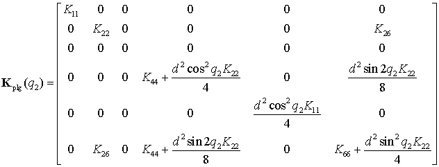
where Kij are the elements of Kbar.
For 3-PUU model, the stiffness analysis was performed for vertices Q1…Q4 of the dexterous cubical workspace 200x200x200 mm3 corresponding to the Orthoglide design specification with the range of the velocity transmission factors [0.5, 2.0]. Besides, similar study was done for the isotropic point Q0 where the transmission factors are equal to 1.0, similar to conventional Cartesian machine [45,69]. For all of these points, there were computed non-linear curves of the force-deflection relations assuming that the displacement is directed along the bisecting line of the coordinate system (this force direction is chosen in accordance to the workpiece orientation in milling application which is currently developing for Orthoglide).
As it follows from the obtained results (Fig. 8, Table 4), for all considered points Q0…Q4, the force-deflection relations are essentially non-linear and include the buckling points where the stiffness reduces radically. Corresponding critical force varies from 4.8 kN for the point Q2 to 15.0 kN for the point Q1, while the critical deflections are in the range 2.1…9.8 mm. The isotropic point Q0 that is usually used for the benchmarks of such manipulators possesses intermediate values of these indices (critical force 9.4 kN and critical deflection 2.7 mm). For all cases, the translational stiffness coefficient in the pre-buckling mode is almost constant, but it essentially varies throughout the workspace. In particular, the highest value 7.1 kN/mm is achieved at the Point Q1 and the lowest one 0.4 kN/mm corresponds to the point Q2. However, after the buckling, the stiffness abruptly reduces down to 0.05...0.4 kN/mm and further, for large deformations, it is about 0.05...0.09 kN/mm. Hence, the traditional linear stiffness analysis (which ignores the influence of external loading) provides rather reasonable indicators for the pre-buckling mode but it does not allow evaluate the range of the loading for which the deflections may be treated as ‘small’ ones and the buckling phenomena do not appear yet.
It is worth also mentioning that for the points Q0…Q3, the physical nature of the buckling is perfectly explained by results from the previous subsection. In these cases, the buckling is cased by sudden change of the configuration of one of the serial chains (from S- or Z- to P-configuration, for instance). However, for the point Q2 that is close to the parallel singularity of the ‘flat’ type, relevant explanation must be revised and will be presented in subsection 6.2.4.
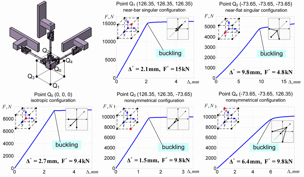
Fig.8 Stiffness of the 3-PUU manipulator in critical points of the cubic workspace
Table 4 Summary of stiffness analysis for 3-PUU parallel manipulators in different workpoints
Configuration |
Stiffness for |
Critical force, |
Critical deflection , |
Stiffness around the buckling. [kN/mm] |
Stiffness for large |
|
|
|
|||||
Point Q0 |
3.35 |
9.35 |
2.68 |
3.63 |
0.05 |
0.05 |
Point Q1 |
7.10 |
15.05 |
2.09 |
7.17 |
0.18 |
0.07 |
Point Q2 |
0.40 |
4.83 |
9.80 |
0.58 |
0.12 |
0.05 |
Point Q3 |
6.26 |
9.77 |
1.48 |
7.00 |
0.10 |
0.05 |
Point Q4 |
1.55 |
9.78 |
6.40 |
1.62 |
0.40 |
0.09 |
For 3-PUcUc model, the stiffness analysis was performed for the same set of the workspace points Q0…Q4 where both of the considered manipulators are equivalent with respect to the kinematic performances. Similarly, for all of these points, the force-deflection relations were computed and the critical values defining the buckling conditions were evaluated.
The obtained results (Fig. 9, Table 5) are qualitatively analogous to the previous ones; in particular, the translational stiffness of the unloaded manipulator varies from 16.6 kN/mm for the point Q2 to 0.4 kN/mm for the point Q1. However, in this case, the numerical values of the critical forces are apparently lower, which slightly reduces advantages of the parallelogram-based architecture demonstrated in our previous publications [42], where comparison was done on the basis of the unloaded stiffness analysis. Thus, in the point Q0, the translational stiffness coefficient is almost the same as for 3-PUU case (3.2kN/mm) but the critical force and deflection are almost twice lower. Similar conclusions are also valid for the remaining points Q1…Q4. Therefore, the parallelogram-based architecture is less robust with respect to the buckling associated to the translational deflections but, as follows from supplementary study, its rigidity is essentially higher with respect to the rotational deformations.
The physical nature of the buckling detected for most of the cases (points Q0…Q3) can be also explained using results for the serial kinematic chains presented in subsection 6.1. However, the parallelograms introduce some particularities that lead to additional bifurcations and salient points on the force-deflection curves. Besides, in the area of flat singularity (point Q4 ) it is required some complimentary analysis.
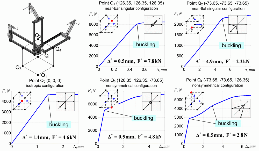
Fig.9 Stiffness of the 3-PUcUc manipulator in critical points of the cubic workspace
Table 5 Summary of stiffness analysis for 3-PUcUc parallel manipulators in different workpoints
Configuration |
Stiffness for |
Critical force, |
Critical deflection , |
Stiffness around the buckling. [kN/mm] |
Stiffness for large |
|
|
|
|||||
Point Q0 |
3.23 |
4.65 |
1.41 |
3.36 |
0.03 |
0.03 |
Point Q1 |
16.60 |
7.85 |
0.48 |
16.40 |
0.42 |
0.31 |
Point Q2 |
0.42 |
2.24 |
4.85 |
0.48 |
0.06 |
0.03 |
Point Q3 |
9.95 |
4.75 |
0.48 |
9.60 |
0.84 |
0.11 |
Point Q4 |
5.41 |
2.78 |
0.52 |
5.09 |
0.65 |
0.06 |
To evaluate specificity of the near-flat configuration, let us consider this case in more details. In order to provide comparability of all case studies, let us keep the same assumption concerning the force orientation (parallel to the coordinate frame bisector) but consider both of two possible directions, i.e. towards inside and outside of the cubic workspace.
The simulation results are presented in Fig. 10 and Table 6 where d0 denotes initial distance from the flat singularity, K0 is the translational stiffness for the unloaded mode, ![]() and
and ![]() are respectively the critical deflection and the critical force for the opposite directions of the displacement. As follows from these results, in the neighborhood of the flat singularity the stiffness properties are essentially non-symmetrical with respect to the force direction. This conclusion is valid for both of the examined models (3-PUU and 3-PUcUc), which demonstrate almost similar behaviors. In particular, for the inside-direction of the loading, the force increases non-linearly but monotonically while the deflection augments. However, for the outside-direction, initially the manipulator reacts to external loading in the same way: increasing of the deflection leads to increasing of the resisting elastic force. But after achieving the critical value, the reacting force begins decrease, the configuration becomes unstable and the manipulator abruptly changes his posture to the symmetrical ones (in kinematics, it is treated as an alternative assembling mode). After that, the manipulator demonstrates stable behavior with respect to the loading.
are respectively the critical deflection and the critical force for the opposite directions of the displacement. As follows from these results, in the neighborhood of the flat singularity the stiffness properties are essentially non-symmetrical with respect to the force direction. This conclusion is valid for both of the examined models (3-PUU and 3-PUcUc), which demonstrate almost similar behaviors. In particular, for the inside-direction of the loading, the force increases non-linearly but monotonically while the deflection augments. However, for the outside-direction, initially the manipulator reacts to external loading in the same way: increasing of the deflection leads to increasing of the resisting elastic force. But after achieving the critical value, the reacting force begins decrease, the configuration becomes unstable and the manipulator abruptly changes his posture to the symmetrical ones (in kinematics, it is treated as an alternative assembling mode). After that, the manipulator demonstrates stable behavior with respect to the loading.
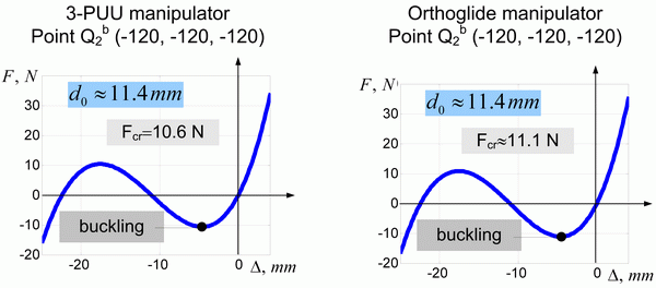
Fig.10 Force-displacement relations for both of the examined manipulators
(neighborhood of the flat singularity; distance to the singularity is 11.4 mm)
Table 6 Summary of stiffness analysis in the neighborhood of the flat singularity
Configuration |
|
Stiffness for |
|
|
|
|
Model A: 3-PUU manipulator |
||||||
Point Q2 |
91.7 |
0.402 |
-3.61 |
-12.6 |
4.80 |
9.8 |
Point Q2a |
46.0 |
0.090 |
-0.67 |
-16.8 |
3.20 |
18.6 |
Point Q2b |
11.4 |
0.005 |
-0.01 |
-4.6 |
2.50 |
36.6 |
Model B: Orthoglide manipulator |
||||||
Point Q2 |
91.7 |
0.418 |
-2.06 |
-5.7 |
2.20 |
4.9 |
Point Q2a |
46.0 |
0.095 |
-0.70 |
-17.1 |
1.45 |
11 |
Point Q2b |
11.4 |
0.006 |
-0.01 |
-4.6 |
0.92 |
24 |
Q2 = (-76.35, -76.35, -76.35); Q2a = (-100, -100, -100); Q2b = (-120, -120, -120) |
||||||
The simplest model that explains the above described phenomenon is presented in Fig. 11. It is derived via generalization of the “toggle-frame” construction known from the structural mechanics, with relevant modifications motivated by the Orthoglide architecture and relative stiffness properties of its elements. Here, the elasticity is concentrated at the basis of the manipulator legs and it is presented by linear springs with the parameter ![]() . It is assumed that initial distance between the end-point and the singularity-plane is
. It is assumed that initial distance between the end-point and the singularity-plane is ![]() , where
, where ![]() is corresponding angle between the leg and the plane. The derived expressions
is corresponding angle between the leg and the plane. The derived expressions
![]()
perfectly describe the shape of the force-deflection curves obtained from the complete stiffness models. Besides, more detailed analysis shows extremely fast reduction of the stiffness while approaching this singularity. Corresponding expressions derived for small value of ![]() yield a linear relation for the critical deflection
yield a linear relation for the critical deflection ![]() and cubic relation for the critical force
and cubic relation for the critical force ![]() . Hence, this simplified model is in good agreement with the simulation results and justifies conventional kinematic design objectives (velocity transmission factors, condition number, etc.) that preserve the manipulator from approaching the flat posture. Besides it proves the common notion of the “distance-to-singularity” that is used in kinematics must be revised in kinetostatics taking into account that loading essentially reduces the margin of the manipulator structural stability.
. Hence, this simplified model is in good agreement with the simulation results and justifies conventional kinematic design objectives (velocity transmission factors, condition number, etc.) that preserve the manipulator from approaching the flat posture. Besides it proves the common notion of the “distance-to-singularity” that is used in kinematics must be revised in kinetostatics taking into account that loading essentially reduces the margin of the manipulator structural stability.
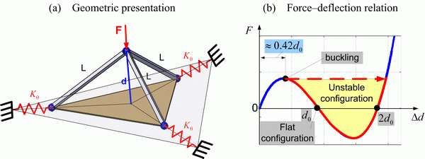
Fig.11 Simplified stiffness model of Orthoglide-type manipulators for near-flat configuration